
If your hardware is already connected and setup, you can skip this step and proceed with Device Cloud setup.
|
|
Detailed assembly instructions can be found within the Quick Start Guide inside the TWR-ELEV module. |
To assemble the tower you will need the following components:
Using these components, connect the TWR-Kxx and TWR-SER boards via the tower elevators (TWR-ELEV). Make sure the primary side (often marked with a white stripe) goes into the elevator board with the white edges.
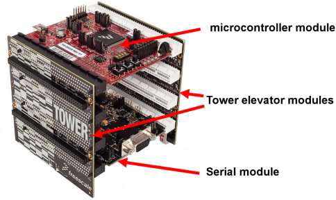
When finished, your tower should resemble the following:
For proper hardware configuration you will need to perform the following changes in the hardware:
| If you'd like to restore default settings after you've completed the steps described within this guide, default jumper settings can be found in the Quick Start Guide for the TWR-Kxx module and TWR-SER modules. |
|
|
The OSJTag firmware should be updated to the latest version in order to take advantage of all the features it offers (such as a virtual serial port). If you have not updated your OSJTag firmware yet, follow these instructions. |